"Railroading on the
Moon" A Design &
Design Exercise
Foreword
In a one column front page piece in Moon Miners' Review # 12, January '93, "RAILROADS on the Moon?", we wondered out loud if someday the degree of development on the Moon would reach a level of population and multi-site dispersal wherein, "in one or more specific surface traffic corridors the volume or raw materials, manufactured goods, or passengers might most efficiently move by rail or some such analogous path-slaved system." We pointed out some of the engineering hurdles that conditions unique to the Moon would place in the way of realizing any such system, specifically the extreme dayspan-nightspan thermal range to which exposed rails would be subjected, and the need to design out any possibility of catastrophic derailment.
We mentioned we had some initial ideas on how we might address such challenges and invited readers to send in their ideas. Several people responded, as you can see from the shared byline above. The exchange between Kokh and Armstrong, meeting in Milwaukee, and MMM Contributing Editor Michael Thomas in Seattle was especially frequent and voluminous. To all those who shared their thoughts with us, many thanks.
Our goal was not to "define" how lunar railroading might someday evolve. That would be presumptuous because there are too many ifs both with respect to the pace of lunar development and with respect to unforeseen technology developments which will almost certainly bear upon the question. Rather, we have attempted to flush out the options that we can see from this point in time. If and when the day comes where something of the sort is realized, some of our suggestions are bound to appear quaint and naive in retrospect. That's an occupational hazard of futurecasting! But we do this for fun.
As we proceed, keep in mind the limited alternative options there are to lunar railroading: travel by surface coach or truck rig over improved graded-paved 'roads' or unimproved trails; travel by suborbital hoppers or rocket shuttles. Period. No atmosphere means no aviation. It is both air travel and the development of a first class network of fast express interstate highways which have brought about the decline of King Rail from the unquestioned ascendancy it had prior to the end of WWII. On the Moon, it could be a whole new story.
CONVENTIONAL OR MAG-LEV?
One of the forward looking solutions that presented itself to several of us is Mag-lev rail in which the rail car hovers over a track, levitated by magnetic forces. This is an especially attractive option for long-distance passenger travel on the Moon. With no right-of-way problems and no atmospheric drag, pressurized cabins as large and wide as or larger than those of 747s could whisk travelers between far-flung settlements in vibrationless comfort at speeds comparable to today's terrestrial airliners. For non-urgent freight, 'conventional' traction railroading solutions might be more cost-effective. But first let us look at Mag-lev.
Two basic approaches are available. In the Japanese System, the superconducting 'ski' of the vehicle is levitated just above the rail by electromagnetic repulsion. In the German system, the superconducting guide plate of the vehicle is suspended just below the rail, held by electromagnetic attraction. [FIGURE 1]
Bill Bogen contributed a sketch of a Maglev car whizzing along across the moonscape. His proposed LunaRail system boasts a number of innovative features. "Bulldozers, graders, and rollers prepare a smooth path over the regolith. Roughly a megaton of Luna-derived aluminum is formed into thin, wide, 'V'-shaped rails for a Maglev train system [below].
* Image awaiting scanner
Besides carrying vehicles, the rails also carry the electricity needed to power the system. This electricity is generated by amorphous silicon solar cells that are integral with the rails, using the aluminum as substrate. Which side of the rail carries the cells depends on the orientation of that rail segment to the sun. The Maglev vehicles pass right over the solar cells, their magnetic fields penetrating through to the aluminum rail below. Given the large day/night temperature differences, we'd need about a 1 inch gap per 10 feet of rail (nightspan) to allow for thermal expansion (the segments almost touching during the dayspan). Flexible accordion connectors join the segments, allowing uninterrupted power flow. [below] Since the 'wheel' of a Maglev is more like a wide ski 'contacting' the rail over a significant area, such gaps would have little effect, assuming proper alignment."
"The rails circle the Moon roughly parallel to, but not necessarily near, the equator, though there may be other lines running to the poles or other regions of interest. Half of the system is in sunlight at all times so LunaRail also acts as a grid that provides power to communities during the 14 day lunar night. Supplying 1 million Lunans with 1 Kw each requires a minimum capacity of 1000 Mw. Since the rails provide power and each vehicle carries its own set of Maglev lift/drive components, there is no need for a separate engine car, eliminating the need for a 'train' [of cars] or the need to connect them. ... The LunaRail track could also serve as a launch-assist system, using 70 Mw to accelerate a payload at 3 g for 81 seconds to an escape velocity of 5,355 mph in a distance of about 60 miles."
Several comments: a) If iron or steel rails are needed as part of a Maglev setup, there is plenty of free iron available in the regolith and a V-shaped iron rail could be loosely sandwiched to the power-carrying aluminum layer (which has a different rate of thermal expansion). b) While aluminum is a good carrier of electricity, line losses over any real distance (hundreds of miles) would be unacceptably great, so that (without superconductivity - see MMM # 66 JUL '93 "SUPERCONDUCTIVITY ON THE MOON, Uses and Obstacles" pp. 5-6) it would be quite impractical to use sunlight over the section currently in dayspan to power the section currently in nightspan. Nuclear or other assist would be needed. c) Power assured by whatever means of generation and transmission, if the superconductor needed for levitation is aboard the vehicle, not squandered along the entire length of track, such a system might still be feasible in the likelihood that an all-lunar formula for superconducting cable or rail is never found.
'CONVENTIONAL' SYSTEMS
PROBLEM ONE: THE CHALLENGE OF THERMAL EXPANSION
While Maglev speed will be most desirable, 'conventional' systems not involving superconductivity may be easier and cheaper to implement, certainly in the earlier period, and may do an adequate job, not only for freight but for high speed passenger traffic. On Earth, system planners are abandoning Maglev dreams for high speed rail almost everywhere, trading a little extra speed for lots of upfront savings cost. Much of the expense in implementing Maglev systems, to be honest, comes with the need to acquire all new Rights-of-Way. On the Moon, this is not a problem and the choice will be made on other grounds.
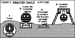
The first challenge to be met with conventional rail is the need to either permanently shade the rails or to provide thermal expansion joints (gaps) that are either undesirably large, undesirably frequent, or both. Michael Thomas has contributed three rail expansion joint designs.
The problem with this approach is that rail gaps, just as rail joint misalignments, translates to the annoying and typical "klickety-klack". Even on the airless, soundless Moon where such sounds would not be 'heard', the accompanying vibrations would be felt. Today's designers of high speed rail are welding together ever longer lengths of rail - an approach not feasible for exposed rails on the lunar barrenscapes.
For this reason, Kokh and Armstrong propose shading the rails from the sun at all times so that expansion is not a problem and continuous unbroken rails for smooth, very high speed travel are feasible. In this system conventional flange wheel trucks would ride in a boxed sun-shielded road bed with an as-narrow-as-possible median slit for the axle to car suspension system. No moving parts would be required for this shading system.
An earlier effort to design a system in which the two rails were individually trenched and shaded by a system of movable 'scales' was rejected as too vulnerable to mechanical failure from dust, for example.
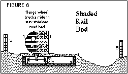
KEY: (1) Passenger a) or Freight Car b); (2) Lunar concrete in steel alloy frame dual shaded rail bed, with welded rails for high speed; (3) Minimal sun-exposed slit for car suspension; (4) well-graded right of way; (5) right of way fencing.
Tunnels are a more expensive option, to be used, as on Earth, to shorten routes through mountain ridges and crater ramparts.
Two other alternatives were looked at. A Lunar "Safege" Type Monorail in which the cars are suspended below a shading track (as at Wuppertal, Germany) rather than supported above it in the familiar Alweg Type systems used in Seattle and Disneyland, etc. [below] While such a system would involve significant overhead construction, it would not directly require any surface grading (except to provide the materials for the overhead superstructure), and it would provide no obstacles for surface cross-traffic by maintaining continuous grade separation. We might see such a monorail favored for short distance passenger traffic, especially in built-up areas where maintaining grade separation between rail and surface traffic is a prime consideration.
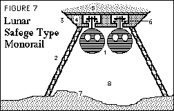
KEY: (1) Passing Passenger Cars; (2) Support Pylons every 50 m or yds; (3) lunar steel alloy framework; (4) lunar concrete for thermal mass; (5) loose regolith fill for thermal insulation;
(6) shaded welded rails; (7) minimally graded terrain; (8) grade separation clearance for surface cross traffic.
A simpler and less expensive system, a 'monopipe' rather than 'monorail' would suspend the vehicle car from unshaded cables or pipes free to expand and contract at dawn and sunset. The up and down valleys and peaks of such a flexible cableway would be greatly minimized by using a suspension system tied to an overhead supporting cable. [below]. Systems of this sort would do fine at more leisurely speeds and be a cheap option in sightseeing areas for example.
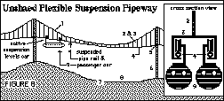
KEY: (1) Suspension Cable; (2) Pipeway Support Cables; (3) Pipe Support Brackets; (4) flexible piperail; with 42 cm (16.5") expansion between Pylons for 0.35 cm (1/7th") vertical droop differential; (5) Piperail floats free at (6) Pylons spaced every 50 m or yds; (7) minimally graded right of way; (8) Surface vehicle cross traffic clearance; (9) Passenger Cars (passing).
PROBLEM TWO: THE NEED FOR DERAILMENT PROOF SYSTEMS
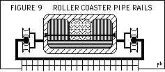
On Earth, derailments are expensive in property damage and, in the case of passenger trains, potentially dangerous to human life. On the Moon you can delete the words "potentially dangerous" and replace them with "almost certainly fatal". A derailed car would almost certainly have its pressure hull compromised, quickly losing life-sustaining air to the external lunar vacuum. In short, the possibility of derailment must be designed out of the system. Both Michael Thomas and Charlie Moore pointed out that amusement park roller coasters use systems in which wheels are paired or even clustered around a tubular track so that the car CANNOT leave the tracks.
The unquestioned safety aspects of such schemes aside, there is a major engineering drawback to them. It is difficult, if not impossible, to design affordable easy-to-operate routine track switching and crossing for such pipe rail hugging systems because the wheel clearance gaps they would require would be too large for the small wheels used to negotiate. As for non-conventional systems mentioned above, a negative center of gravity (i.e. below the rail) is built into the monorail and suspensionway option. The monorail is inherently derailment-proof. The suspensionway is inherently derailment-resistant.
To meet both switching and safety needs, Kokh and Armstrong then proposed a "Center Box Rail" system in which a restraining bar, plate, flange, or pair of small wheels would ordinarily float free of contact. If the car 'started' to lift off one rail and threaten to leave the track, the center restraining bar would come into contact with the slit top of the center box rail.
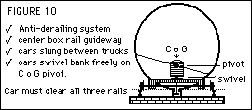
NOTE: In this illustration, the design is maximized for minimum center of gravity and anti-derailment strength. It does not take into consideration the need to shade rails.
This third rail would lie in the same plane as the other two and its median slit need be no wider than the clearance needed for the side wheel flanges, making even grade RR crossings a simple matter.
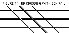
NOTE: In this illustration, the minimal gaps needed for conventional flange wheels and for the restraining device in the center box rail are shown.
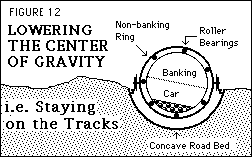
An alternative proposal of ours was to suspend the rail car from the waist in a concave trough so that its center of gravity was actually lower than the side rails. The car's suspension would include flotation rings that would allow it to bank freely. The trouble with this idea is that it would again make switching difficult.
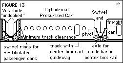
In another attempt to design a low center of gravity derailment-resistant system, we borrowed the Spanish idea of putting the wheel trucks between the cars, not under them, so that the cars could maintain minimal clearance with the rails. Again, this system would not combine well with our shaded rail bed idea, but would work in tunnel applications or under continuous shade sheds or ramadas.
In the back and forth exchange of ideas that made this effort a lot of fun, Michael Thomas took pains to elaborate the possible applications of all these ideas and came up with a number of interesting sketches of which three which show the breadth of his design search are given below. In FIGURE 14, Mike has combined the advantages of the shaded rail concept with those of the center box rail restraint system and come up with a "Flat Bed Quad-Rail". It introduces the idea that rails 'above' the wheels can be used to constrain the train's motion. A second upper set of wheels is desirable because wheels coming into contact with the upper rail need to turn or free-wheel in a direction opposite those riding the lower rail.
* FIGURE 14: A FLAT BED QUAD-RAIL (to be scanned)NOTE: The size of the wheels is greatly exaggerated to show the arrangement in more detail. KEY:
- 1) Concrete or Ceramic overhang and rail support.
- 2) Upper rails for inside-flanged wheels
- 3) Upper wheel with inside flange
- 4) Lower wheel with outside flange
- 5) Inter-carriage wheel truck
- 6) Pressurized car
- 7) Pivot attachment point to wheel truck.
- 8) Lower rails for outside flanged wheels)
In FIGURE 15, he uses the same "quad rail" restraining concept together with a concave road bed and overhead shading.
FIGURE 15: A CONCAVE BED QUAD-RAIL (to be scanned)
KEY: Same as for Figure 14 above.
FIGURE 16: (to be scanned)
In FIGURE 16, Thomas depicts an extra wide road bed with a center box rail support together with lowering the ratio of the center of gravity to the track width by supporting two cars side by side on a single double width chassis. Shading is provided by a lightweight arch shed built of lunar concrete blocks.
In last analysis, the simplest, most elegant, most cost effective designs will win out. Some solutions that we have not foreseen are sure to surface in the future with the introduction of new technology.
CONCEPT OF THE "TRAIN", SEVERAL CARS LINKED TOGETHER
In terrestrial passenger trains, we are accustomed to being able to walk the length of the train, from one car into the next, without being exposed to the elements, thanks to flexible accordion like "vestibules" linking the cars. In lunar conditions, not only shelter but pressurization against the external vacuum must be maintained, and this would be difficult to manage with a flexible system constantly bending up, down, left, right - difficult, but not impossible. After all, the spacesuit joint manages the same task fairly well. Yet no spacesuit has undergone the 'mileage' of constant use to which rail equipment must be subjected.
"Vestibulated trains" may be an unlikely denizen of future lunar travelways. Instead, given both the economic possibility of much wider Rights of Way, and consequently of much wider track gauges, and the lack of the need for streamlining against air resistance, plus the lower gravity on the lunar surface, single double and triple width, double and triple decker, and double and triple length rail cars are feasible - more on a par with today's Boeing 747 cabin than what we are now used to riding on the rails. This will hold of both conventional rail systems, overhead monorails, and Maglevs alike - as the traffic volume warrants.
On the other hand, as we attempted to illustrate in FIGURE 13, we might see instead a "train" of more conventionally sized cars, all equipped with vestibules which, however, would be undocked with one another while the train is in motion, but "dock" together when the train is standing motionless in the depot on straight and level track. This would allow boarding and unboarding through the end car (trains backing into the depot) instead of requiring a series of docking ports, one for each car's side port.
LOCOMOTIVE POWER OPTIONS
We were unquestionably more preoccupied with the design challenges tackled above than with the question of motive power for lunar trains. After all, the options here seemed to be more clear, less in need of brainstorming. Rails could be electrified, the power coming from a combination of trackside solar arrays and solar power satellite in the L4 and L5 Lunar co-orbital fields and/or from nuclear( or thermonuclear i.e. He-3 fusion) plants. An all-lunar formula for superconducting cable would certainly help but seems at this juncture unlikely. An alternative would be to use satellite-laser-beamed power directly to individual rail cars and trains.
In the honeymoon days of nuclear power (yes, youngsters, there was such an era us oldsters dimly recall), the coal-dependent Norfolk and Western seriously considered a nuclear powered locomotive. After all, weren't nuclear reactors being put aboard submarines? If the shielding problems can be solved to everyone's satisfaction, this could be a sleeper option. A more remote sleeper is onboard fusion power. At this time we don't have a high degree of confidence nuclear fusion can be engineered at all. It is quite premature, then, to speculate how compactly He-3 fueled locomotive power packs could be built. The advantage would be that, in contrast to conventional nukes, they would need little or no shielding, a very attractive prospect.
To many, our nation's space program being industriously disassembled before our very eyes by a Congress and Administration preoccupied with other priorities, the idea of railroading on the Moon must seem sheer folly, unrestrained fantasy. But the government could never open the Moon anyhow, so these setbacks are irrelevant. If the Lunar Resources Data Purchases Act is passed, and our expectations about exploitable lunar resources are borne out, and as Earth's energy options dwindle and environmental constraints tighten, we WILL return to the Moon with or without government help or approval, out of sheer economic necessity. That is the only motive worth considering and boosting - yet the one most neglected by space advocates.
Once we clearly HAVE TO go back, and do so, the pace of economic development on the Moon, and in space in general will explode far beyond what almost anyone dares dream today. Someday there WILL be thousands of people on the Moon, not a mere token elite handful, THEN hundreds of thousands. It will be in such an era that LunaRail lays its first stretch of track, bound for a future with much less competition than rail has had here on Earth.
Thanks again to all who took part in this first round of brainstorming on this question. Those of you who didn't participate but now have something to add to the discussion, are certainly welcome to do so. Just write to MMM/MMR c/o the LRS P.O. Box 2102, Milwaukee, WI 53201-2102.


