|
"The Frontier Builder" An Earth-Moon Hotel Cruise Ship DEFINITION AND DESIGN EXERCISE © 1992 Doug Armstrong and Peter Kokh, LRS Design Team |
A DESIGN EXERCISE
It was not our intention to design our Transitel down to the last rivet and cubbyhole. Rather we wanted to do just enough "architectural" work to validate our definition concepts and to ferret out major lurking problems. Accordingly the illustrations below are meant to be just that: illustrations or suggestions. You take it from there.
SIZING & PARAMETER ASSUMPTIONS
× Spin Radius 144 meters or 472 ft
× 1/6 G at 1 R PM
× ETC (shuttle External Tank Compatible) modules 27.5 ft in diameter (plus meteorite cushion) x 150 ft in length.
PASSENGER CAPACITY ASSUMPTIONS
Our aim was a 200-300 person capacity. The three ET-Compatible Hotel Wing Complex illustrated (one accommodations module per shift (=2) and one Hotel Functions Module) would seem to come in on the high end of that capacity range. The critical question here is to mate the transitel capacity to that of the shuttle cabins bringing in and taking off guests. If necessary, the complex illustrated here can be downsized, or alternately more generous function space can be provided, replacing some of the suggested passenger quarters, and/or fewer passenger quarters with more space each.
BASIC ARCHITECTURE
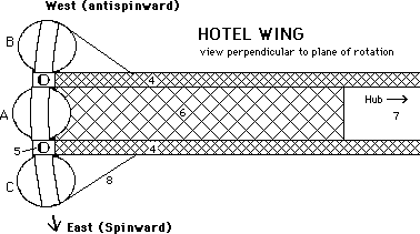
(A) Hotel function space; (B) & (C) Passenger Quarters. Hotel Wing ETCs are attached sideways (horizontally) to the elevator backbone structure so that the decks run end to end. And they are oriented perpendicular to the plane of rotation to minimize floor curvature needed for orientation. Note: Decks of Transitel Cylinders showing curvature necessary to maintain perpendicularity to the floor. At 145 meters (about 475 ft.) and with a mid-deck width of 27 ft. this curvature from sidewall to the center of the deck would be about 2.3 inches. If the long axis of the cylinders lay in the plane of rotation instead of perpendicular to it. The potential rise in curvature (or need for adjustment by split-leveling) from mid to end point for a 140 ft. long cylinder would be 5 ft 1 inch. KEY: (4) twin elevator shafts and structural booms. (5) pressurized elevator. (6) trusswork between elevator shafts. (7) structure free central bay for shifting hub. (8) guy wires/support cables.
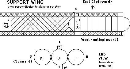
E) & (F) Energy & Utilities; (D) Farm. Support Wing ETCs mounted vertically for more efficient function-oriented use of flat deck space and vertical walls. (4-7 as above).

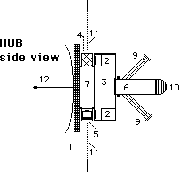
(4) Twin elevator shafts (also hosting pipelines, cables, pneumatic tubes etc.) are the tie that binds the spinning Transitel ensemble. Cross Braces strengthen sides, not cavity, of twin elevator boom. The two shafts are in the plane of rotation, with the center of rotation somewhere along the way between them. The twin shaft boom is long enough to maintain an average 145 meters between the lower mid-deck of the Hotel Wing and the floating Hub Core (3). The average actual distance from floating hub to the Service Wing depends upon the weight ratio of the two sections, which need not be maintained at 1:1. Hub core free-floats the rails along the inside edges of the twin elevator shafts. A pair of gravimetric sensors attached to the hub rail-riding mechanism in each direction along the twin elevator shaft boom allows it to find and follow the actual center of rotation, no matter how the masses are split between the two ends of the "dumbbell". As weights shift, either the nominal 1/6th G gravity level can be allowed to shift as well, or the nominal 1 RPM can be shifted by a flywheel to compensate for shortening or lengthening of the Hotel Wing to hub radius. The hub core has docking port complex (6) for visiting Earth and Moon shuttle-craft cabins (to serve as potential lifeboats while docked), and freighters. (7) Central Bay is free of cross bracing (8) to allow free floating room for hub core. Hub core is linked between the elevator shafts to the co-floating flywheel-shield complex (1). (5) A pair of Transfer gates along with the Rendezvous Vestibule towards the outer rim of which they are placed, are spun up from 0 RPM to 1 RPM coming to rest with its transfer airlock over the elevator shaft. Elevator cage (5) is shown in position at one gate. Cage with weighted free-pivoting pressurized compartment stops opposite airlock of transfer gates in Rendezvous Vestibule for passenger transfer. The stop is triggered by the floating presence of the transfer gate, not to a fixed position on the elevator shaft.
(4) Twin elevator shaft booms, (7) trusswork-free central bay, (3) Rendezvous Vestibule is the stubby cylindrical base section attached to the hub core (6) "North" ("Neptune-ward") of the elevator shafts (depending on orientation) along the axis of rotation. Concentric to the vestibule are the (flywheel-shielded) quarters of the permanent staff (2), and the elevator transfer doors (5). (9) O RPM docking ports for shuttle cabins, supply freighters (10) 0 RPM passenger-available stellar/planetary observatory. (11) "Equatorial" plane of rotation of the Transitel complex. (12) Possible solar turbine (also shades flywheel, if desirable). FLYWHEEL OPTION: a small flywheel at core of shaded area with wastewater in treatment phase (available germicidal UV) filling shield proper.
FLOATING HUB CONCEPT:
The premise architectural decision was to use a fixed boom rather than a tether which would have required spin down to 0 rpm for docking, embarkation & debarkation. It was next decided to twin the elevator shaft with a 27.5 ft wide bay between (to straddle central ETC module at each end). This adds redundancy, safety, and stability. And twined in the plane of rotation instead of along its axis, a means of bypassing the vertiginous hub en route from one wing to the other, so that those riding in a weighted pivoting capsule would always sense some up-down relative to the center of rotation. The twin booms also host à pipelines for volatiles, à cables for electrical power, even à pneumatic tubes for containerized item transfer between the two wings.
By confining the truss structure connecting the twin elevator shafts to either end of a central open bay, room is provided for the hub complex to ride rails on the inner edges of the elevator shafts so as to compensate for weight shifting between the Hotel Wing and the Service Wing within fairly generous limits, thus keeping the physical hub at the actual center of rotation. Gravimetric sensors on the co-rotating part of the hub riding the shaft rails would be coupled to electric motors to keep the hub precisely on center of mass.
The Hub Vestibule would have elevator docking doors where transfer from spinning boom to despinable hub and vice versa occurs at a comfortable distance from the flip-flop point.
If necessary, a counter-rotating flywheel floating the boom rail on the opposite side from the transfer hub, could dissipate torque, and serve as spin-up/spin-down mechanism, and do double duty as flare shield. A flare shield 2 meters thick and 60 feet in diameter sunward of the twin booms and opposite (floating with) the hub/transfer vestibule (= storm shelter) and staff cabins, made of compacted and sintered lunar regolith would weigh over 3,000 tons and be slow rotating. Or this shield could be non-rotating and concentric to a fast rotating denser flywheel. (One 1 meter thick, 1000 tons, at a mean radius of 15 meters would have to rotate at only 10 rpm to counter 2x500 tons at 150 m and 1 rpm. A 100 ton flywheel would call for 100 rpm. A 10 ton flywheel 1000 rpm, and so on.) If these options are unacceptable, rockets at each countermass can effect the spin-up/down.
DETAILS OF THE HOTEL WING

Hotel Plan - 1 LOBBY - Corridors to Passenger Corridors in flanking Modules; 2 Grand Staircase - open; 3 Balcony over lobby - photo gallery - Transitel construction and history - future successors; 4 PURSER's office, Gift shop; 5 BRUNCHERIE: Breakfast and Lunch (2 sittings), arrow points to solar clerestory; 6 LIBRARY - 7 Meditation Chapel (stained glass windows facing Sun); 8 DINER (1 sitting) 8C crew class, 8T tourist class, 8L luxury class near Starfield Window; 9 U of Luna Campus Hall - Theater; 10 Barber, Hairdresser; 11 INFIRMARY - Hospital; 12 GAME Lounge; 13 BAR Lounge; 14 Massage, Jacuzzi, Sun room; 15 SPORTS coriolis courts & shared time GYM & Exercise room; 16 KITCHEN showing dumbwaiters to Diner and Bruncherie, cupboards, and stairwell; 17 Elevator to Hub and Support Wing
Note: additional hotel function space might be located on the middecks of the passenger quarters modules (accommodations modules) adjacent to the lobby and elevators.
Passenger Quarters (Accommodations) Module
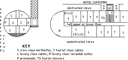
Portholed outside cabins: those facing the hotel module might be for Tourist Class. Those with unobstructed starscape views for Luxury Class, the end cap suites with "verandahs" reserved for Regency Class. According to this drawing, each Tourist/ Luxury floor might have 13 Tourist rooms, 7 Luxury rooms, and 2 Regency verandah suites. At two floors per each accommodations modules, and double occupancy this gives room for 176 non-crew passengers plus some children.
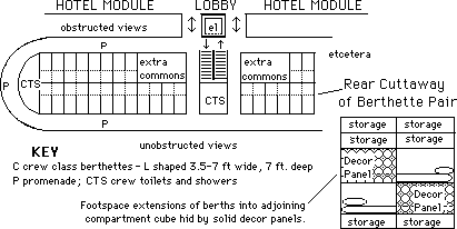
As shown, there would be 40 single occupancy crew class berthettes on the promenade deck of each accommodations module for up to 80 crew class passengers in all. This provides a 2.2 to 1 passenger to crew ratio. Cruise ships operate in the 2.1 to 2.8 ratio range. Replacing two more pairs of berthettes with additional extra hotel function space handy to the lobby, stairs, and elevator would reduce the number of berthettes and crew class passengers to 72 for a 2.44 to 1 ratio.
This leaves us with the following: Permanent Staff 7; Regency class 16; Luxury class 56; Tourist class 104; Crew class 72. Total Capacity 255 double occupancy With room for some children we are talking about a ship which could carry 250-300 people.
IDEA FOR A 1/6th G "MOONSCAPE"
for EVA simulations by passengers making the loop of the Moon but not going down to the surface for an extended stay.
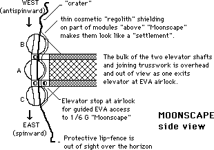
SIDE VIEW: The simulated Moonscape platform is the thick curved line following the hub-centric gravity gradient. The footprintable "regolith" need not be more than a few inches deep, keeping the mass involved small.
Portholes of Tourist and Luxury cabins on the top deck of both Accommodations Modules would look out on the "Moonscape". Even the top of a protective lip or fence would lie over the horizon, as seen from most of Moonscape.
Those on the outside lower decks of the Accommodations Modules would look out and up to see only a flat black underside to blend in with the starry background of space. While there will undoubtedly have to be some sort of structural reinforcement for the cantilevered mass of the "Moonscape" Platform, the 1/6th G will (even the 3/8 G attained on occasional Mars theme cruises - where "red" floodlighting could help change the apparent venue) should keep this to an unobtrusive minimum.
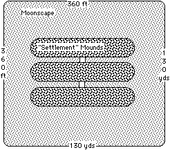
PLAN or top-view of 3 acre Moonscape, showing simulated lunar terrain in light gray and "settlement shielding mounds" over protruding Hotel Wing Modules in dark gray.
P.S. ON THE CHOICE OF ET-COMPATIBLE MODULES
The standard Shuttle External Tank may be the most conservative choice but it needs to be retrofitted in orbit at astronomical labor costs. The optional "ET Compatible" is launched ready to use in a Shuttle-S configuration with its own SRBs and SSME pod strapped to a standard ET-SRB complex. This allows à on-the-ground outfitting (including meteorite/debris shield) without restrictions imposed by ET structure other than general size. à One hull-tank (with nose faring) can replace the two-tank structure of the current ET. Greater versatility: à more room for portholes and observation caps e.g. under nose faring. - Meanwhile , à standard hydrogen and oxygen ET tanks and intertanks could be used as additional components where needed.
The inflatable option would allow cylindrical modules larger than 27.5 ft. in radius. But this is an as yet undemonstrated technology especially as to the challenge of maintaining structural integrity along with a large number of portholes etc. which might either be built-in or added subsequent to inflation and foam-rigidization.
Space Construction, the most ambitious option implies a space based construction facility such as may not be available for some time. This prerequisite would delay the dawn of Earth-Moon Hotel Cruise Ships or Transitels for some time.
CONCLUSION
For the two of us, this was very much a fun exercise and one from which we learned quite a bit about the shape of things to come. Such a vehicle-hotel would serve to accelerate the opening of the Lunar Frontier to settlers and tourists alike, as well as promote popular support among the Earthbound. We think the Crew Class provision is worth pursuing.
"The Frontier Builder" as illustrated above may never be built. But some of the ideas developed herein may see light of day. We feel we have made a definite contribution in our concept of a "floating hub". Finally, we invite others to join us in future design-definition projects. DA & PK

