
Solar Power
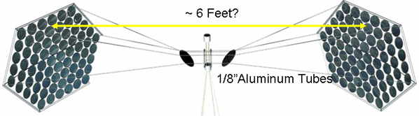
Beaming Demonstration Unit
Left, Right Main Mirror Assembly
by Peter Kokh
Left, Right Main Mirror Assembly
by Peter Kokh
| Main Mirror Assemblies | Center Mirror Assembly | Wood & Wire parts |
| Working Parts | Overall Assembly Directions | Shipping & Packaging |
| Online Kit Home |
These instructions were not provided and have been put together by examination of the finished product
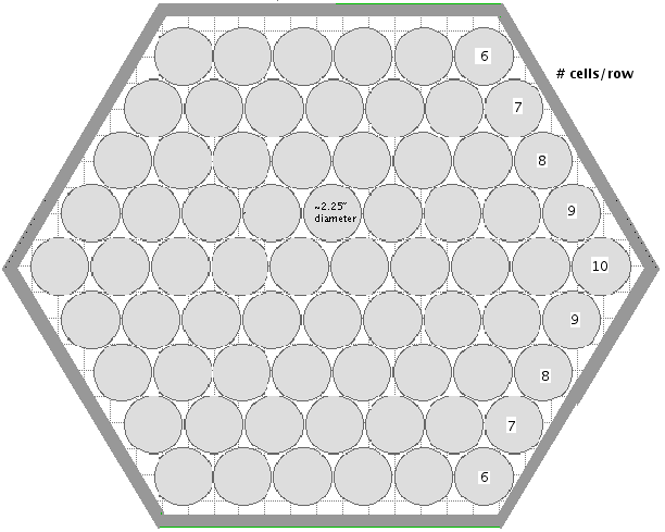
Illustration of the Left, Right Main Mirror Assemblies
These consist of a "gasket" covered on one side with aluminum foil, the dull side adhering to the gasket, shiny side "sunwards." These gaskets are approximately 2 1/4" in outer diameter, 1 3/4" in inner diameter or 58 and 44 mm respectively. The gasket material used is polystyrene sheet 0.3 mm thick. Each one individually traced with a template and then cut out.
The important thing is that they are arrayed in staggered rows of 6, 7, 8, 9, 10, 9, 8, 7, 6 - illustration below.
There are 70 of these cells in both the left and right main mirror assemblies.
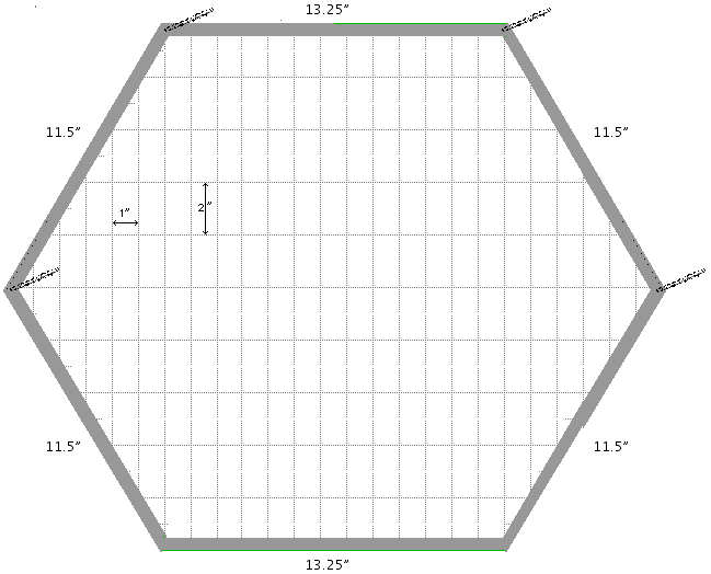
We suggest that you first make the "gasket" solar cell units from polystyrene sheet, then arrange them on a flat table in the pattern above, and then determine the inside measurements you will need for the hexagonal frame shown in gray above.
The outer dimensions of the original unit are 111.5" (29.2 cm) on the 4 side sections, and 13.24" (33.5 cm) on the top and bottom sides of the hexagon. The angles are all 60 degrees. That the top and bottom sides are longer are determined by the shape of the 6-7-8-9-10-9-8-7-6 staggered rows of cells.
If you use premade gaskets of a similar but slightly different size, the frame you make will differ accordingly in dimension from the above. Sources of pre-made gaskets? Plumbing supply stores? Automotive supply stores?
The framing bar material is also fabricated from polystyrene sheet 2 mm thick, cut out and sandwiched together to make the double thickness bars. Phil Mills sandwiched the wires to anchor them with more of the 2 mm sheet, with the inner piece in segments around which the wire frame wire (fishing line) that supports the individual solar cells, are wound. Below is an illustration of the support wires. The assembled frame "bars" are approximately 1/4" thick and 1/2" wide.
The polystyrene sheet should be found at all good Hobby/model/ model railway shops. The source is Evergreen Scale Models, 18620-F 141st Ave, NE, Woodinville, WA 98072, Toll Free: 877-376-9099 Fax: 425-402-7948. www.EvergreenScaleModels.com
Note that the spacing is designed to fit the spacing of the supported individual solar cells. Please adjust this spacing to fit the size of the gaskets you are using to support the solar cells, whose backside (dull side with gasket exposed) is glued to the wire frame. The above wire spacing dimensions reflect the size of the gaskets used, when in a staggered arrangement.
Problem: The adhesive used in the original was a clear contact type adhesive, UHU all purpose adhesive to be precise. It was spread on the fishing line grid and the disks were attached one by one. In retrospect, this adhesive does not bond well enough, as with each display of the SPB unit, we have had to reattach a number of cells that have come loose. Alternative adhesives? Possibly a clear 100% silicone adhesive which is available in a small toothpaste style tube at most hardware stores and home centers.To the assembled frame are attached four 1/8" hollow aluminum tubes, 2 inches long each. They are attached with an adhesive in a 60 degree slant to the right, in the left mirror assembly unit, and to the left, in the right assembly unit. No tubes are attached to the bottom angle intersections of the frame. These tubes take the wire rods that connect these arrays to the Center Mirror Assembly.
Hollow aluminum tube source: Try model shops especially model railway specialists. Most model shops should sell them and they are manufactured in the USA. Those used in the original are from K&S Engineering Chicago IL.Problem: the 2" long 1/8" diameter aluminum tubes mounted on the Solar Solar Disk (4) and on each of the Main Mirror Assemblies (4 each) at an angle are glued in place and easily knocked off.
Experimentation is recommended with drilling holes of the proper diameter and at the proper angle into the Main Mirror Assembly frame and the Blue Solar Disk frame so that these tubes can be inset not only to secure their adhesion, but to secure their proper angle.
We have tried "fast epoxies" which are no where near fast enough or solid enough. We recommend trying Plumbers Epoxy which gets rock hard in a hurry and sets for life (if not forever, i.e many lifetimes.) We further recommend securing a small surplus of these 1/8" diameter aluminum tubes, precut to 2" lengths. Once one breaks off, the chances of finding it are not in your favor.
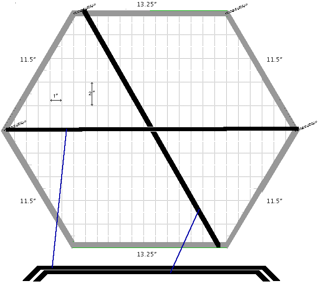
Making the rear support frame.
There is one support frame behind the center row of 10 solar cells and another from the upper far corner (with respect to the Center Mirror Assembly) to the lower near corner. The center bar extends further back, behind the slanted support bar.
The clearance of the inner bar is 3/4" and of the outer bar 1 1/4"
Where they cross one another, the junction is bound by wire.
Problem: These polystyrene bars and frames can break. We have used duck tape to mend the seams, but this does not guarantee alignment. Polystyrene is lightweight. But perhaps an aluminum frame would provide longer trouble-free service. Do explore other options.
© 2008-2009 The Moon Society
