
Project Status
Table Top Solar Power Beaming Demonstrator Project
Updated May 11, 2008
Project Definition
As indicated in the project Home Page, the table-top demonstration project will be conducted in three phases:Phase 1
In Phase 1, a design for the table top demo system will be developed and cost estimates prepared for the remaining Phases.Phase 2
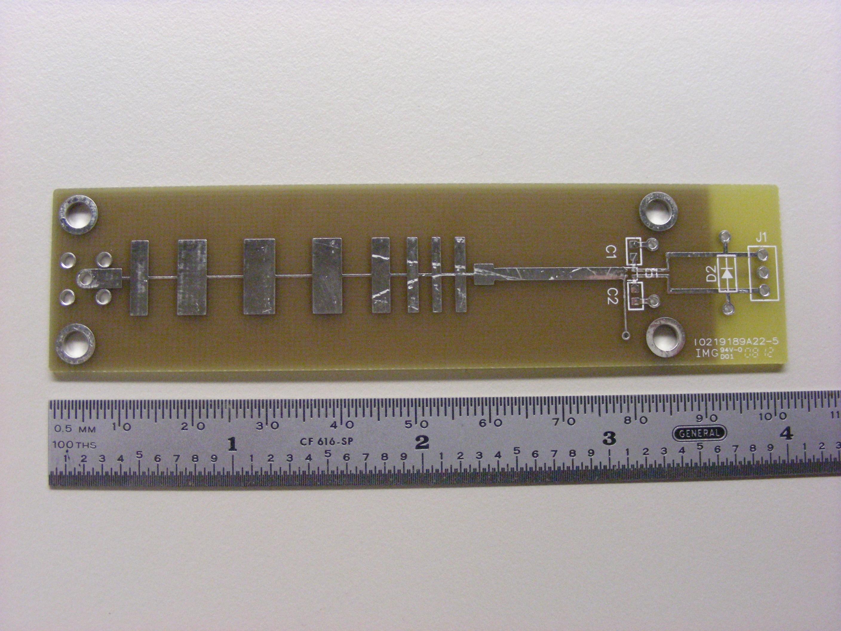
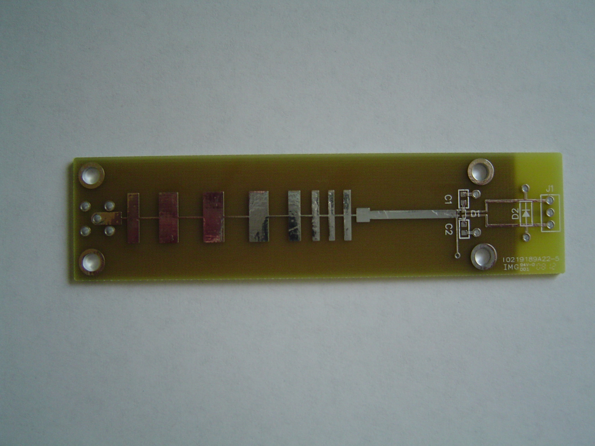
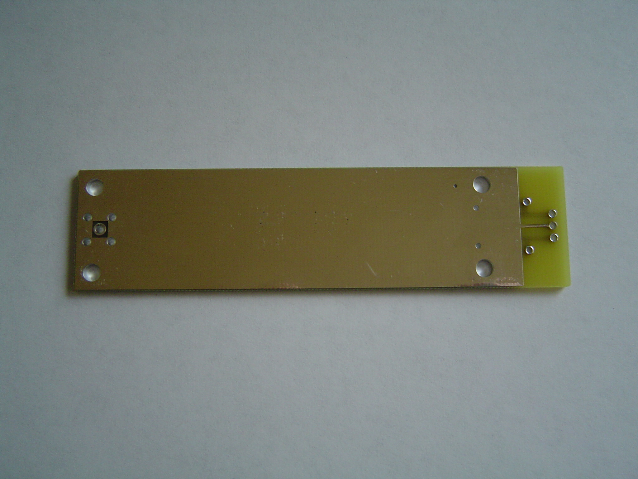
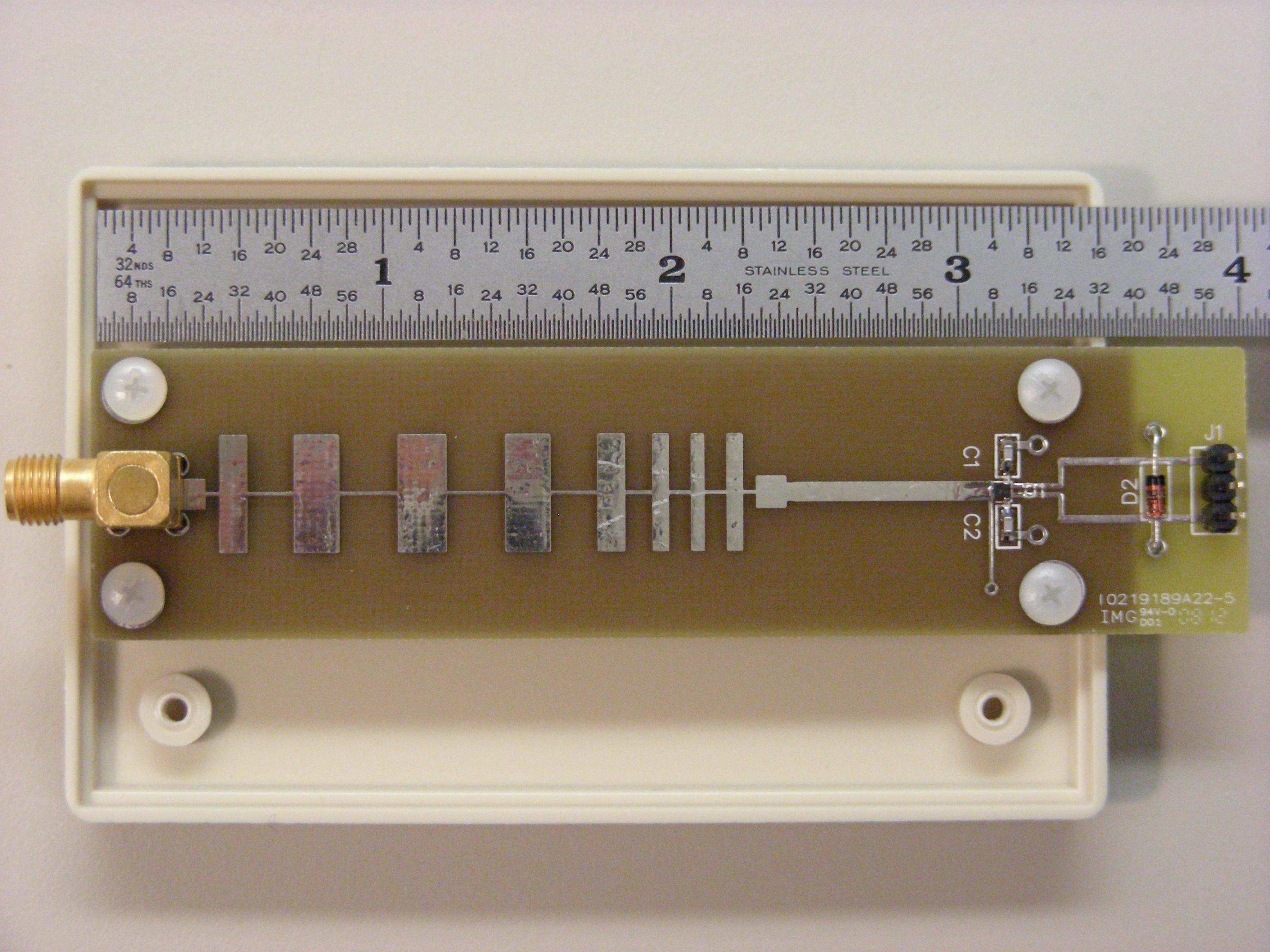
In Phase 2, one complete working prototype of the system will be constructed and performance will be measured to verify that project goals are met. On completion of Phase 2, the prototype will be available for use as a demonstrator. It is likely that a small quantity of the custom made parts will be obtained at the same time as the prototype parts to gain more favorable pricing.View of the top and of the bottom of the bare rectifier circuit board priorto mounting components.
Phase 3
Phase 3 will construct a number of copies of the system for distribution to interested parties. The quantity has not yet been determined.Project Status
Phase 1
Work was begun on Phase 1 in late November, 2007 by volunteers Charles Radley (Moon Society Vice President), Scotty Gammenthaler (Moon Society Chairman), and Philip Mills (Space Frontier Foundation). The following tasks are being performed:| Item | Assigned to | Status |
| FCC Rules | Charles and Scotty | Completed |
| FCC rules permit operation at a number of frequencies under the provisions of CFR 47 Part 18 - Industrial, Scientific, and Medical Equipment. Certain frequencies permitted under this part are also subject to limitations underCFR 47 Part 15. (See 15.247 and 15.249). After review, 2.492 +/-8 GHz and 5.862 +/- 8 GHz were identified as being within the Part 18 (ISM) allocation and outside the additional limitations of 15.247 and 15.249 and meet the other criteria imposed by size limits and availability of low cost components. Equipment to be operated under Part 18 requires FCC approval in the form of verification. (See 47 CFR Part 18.203(b) and Part 2.902) However, the rules permit operation of equipment that has not been approved for demonstration purposes so long as the equipment is not sold or offered for sale (See 47 CFR 2.803). In this case the equipment must be accompanied by a conspicuous notice stating: | ||
| Safety Rules | Charles and Scotty | Completed |
| Maximum permissible radiofrequency radiation exposure limits (MPE) are specified by the FCC in CFR 47 Part 1, Subpart 1310. Other bodies also have MPE limits but the FCC limits seem to be the definitive and enforceable standard. At either of the frequencies identified above, the MPE is 5 milliwatts/cm^2 averaged over a 6 minute period for occupational or controlled exposure in which persons are fully aware of the potential for exposure and can exercise control over their exposure. In cases where persons may not be fully aware of the potential for exposure or can not exercise control over their exposure, the MPE is 1 milliwatt/cm^2 averaged over a 30 minute period. Because of the nature of the demo system, it is believed that the controlled exposure limits should apply provided that a notice is posted with the demo system and the system is operated by a person aware of the exposure. (This assumes that the power density outside the immediate transmission path is below 1 milliwatt/cm^2 so that exposure of casual bystanders is below the uncontrolled limits.) | ||
| Liability Issues | Charles | Completed |
| Charles has identified a registered professional engineer who is willing to approve the design provided certain testing and analysis requirements are met. This will permit obtaining professional liability coverage | ||
| Choose a preferred operating frequency | Charles and Scotty | Completed |
| After considering all of the factors, 2.492 GHz appears to be the best choice. | ||
| Availability of off-the-shelf components | Scotty | Completed |
| It appears that all of the components needed to build a demo system are available off the shelf for the 2.492 and 5.862 GHz bands except the rectifier and stand. Costs are significantly higher for 5.862 GHz so 2.492 GHz is preferred unless other reasons are found to utilize 5.862 GHz. It will be necessary to design a custom rectifier circuit to obtain the characteristics required for the rectifier portion of the rectenna. The stand is inherently a custom-made component. | ||
| Perform system design | Scotty | Completed |
| A study of antenna characteristics was conducted and the results are available at Antenna_Relationships.pdf. Conclusions reached in this study indicate that it should be possible to meet project goals at 2.492 GHz but it is not possible to accurately predict coupling between antennas at the spacing proposed for the demo system. Coupling measurements were made on two different antenna configurations and the results are at Antenna_Coupling.pdf. These measurements show that best results are obtained at short distance (less than 10 inches flange-to-flange spacing) usingthe same 14 dBi gain antenna (8 1/2 x 8 1/2 inches) for both transmit and receive, while better results are obtained at greater spacings using the 14 dBi antenna for transmit and a 19 dBi gain antenna (15 x 15 inches) forreceive. A system block diagram using the pair of 14 dBi antennas is at Power_Beaming_Demo_Block_Diagram.pdf.Final choice between these two configurations will be made after completion of the prototype electronics. | ||
| Find a contractor capable of fabricating and testing the system | Charles | Completed |
| Design of custom made electronics | Scotty | Completed |
| Simulation and analysis of rectifier circuits were conducted in a two-part study available at: Rectifier_Relationships_Part_1.pdf and Rectifier_Relationships_Part_2.pdf The documentation required to fabricate the rectifier is available at: Rectifier_Fab_Files.zip This includes Gerber photoplotting files for the circuit board artwork, mechanical drawings for an enclosure, and a parts list. Note: Our contractor has suggested that it will be less expensive to use an off the shelf plastic box with minor modifications for the enclosure and we may use this option. | ||
| Design and model the stand | Philip | In Process |
| Philip Mills has constructed a model and prepared drawings for the stand. | ||
| Estimate costs of the remaining phases | Scotty, Charles, Philip and contractor | Completed |
| Our contractor has submitted an estimate of $860.00 to build one complete set of electronics plus $30 for each additional rectifier. These costs do not include fabrication of the stand. It is estimated that additional copies of the system can be built for about $750.00 each. | ||
Phase 2
The Moon Society approved a budget for Phase 2 at the March 19, 2008 meeting ofthe Management Committee and work has begun to construct the prototype. We are aiming to have the prototype completed before the ISDC 2008 conference in Washington D.C. at the end of May and intend to demonstrate the system at the conference. A prototype circuit board for the rectifier has been received and other parts are on order. The following pictures show progress on assembly and test of the system:Rectifier circuit board before mounting components: Top Side Bottom Side |
Assembly of the electronics was begun on April 10 and completed on April 30, 2008.
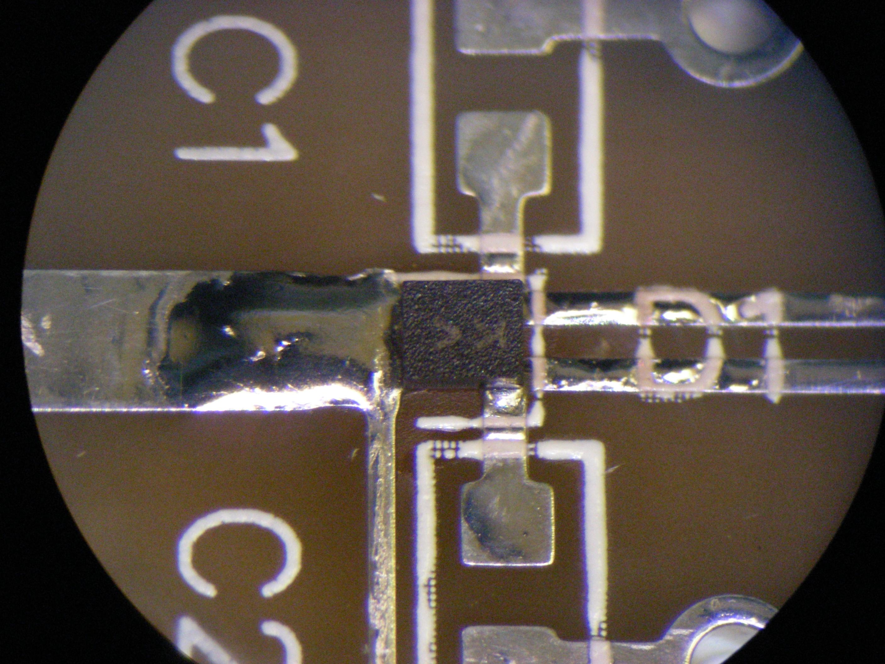
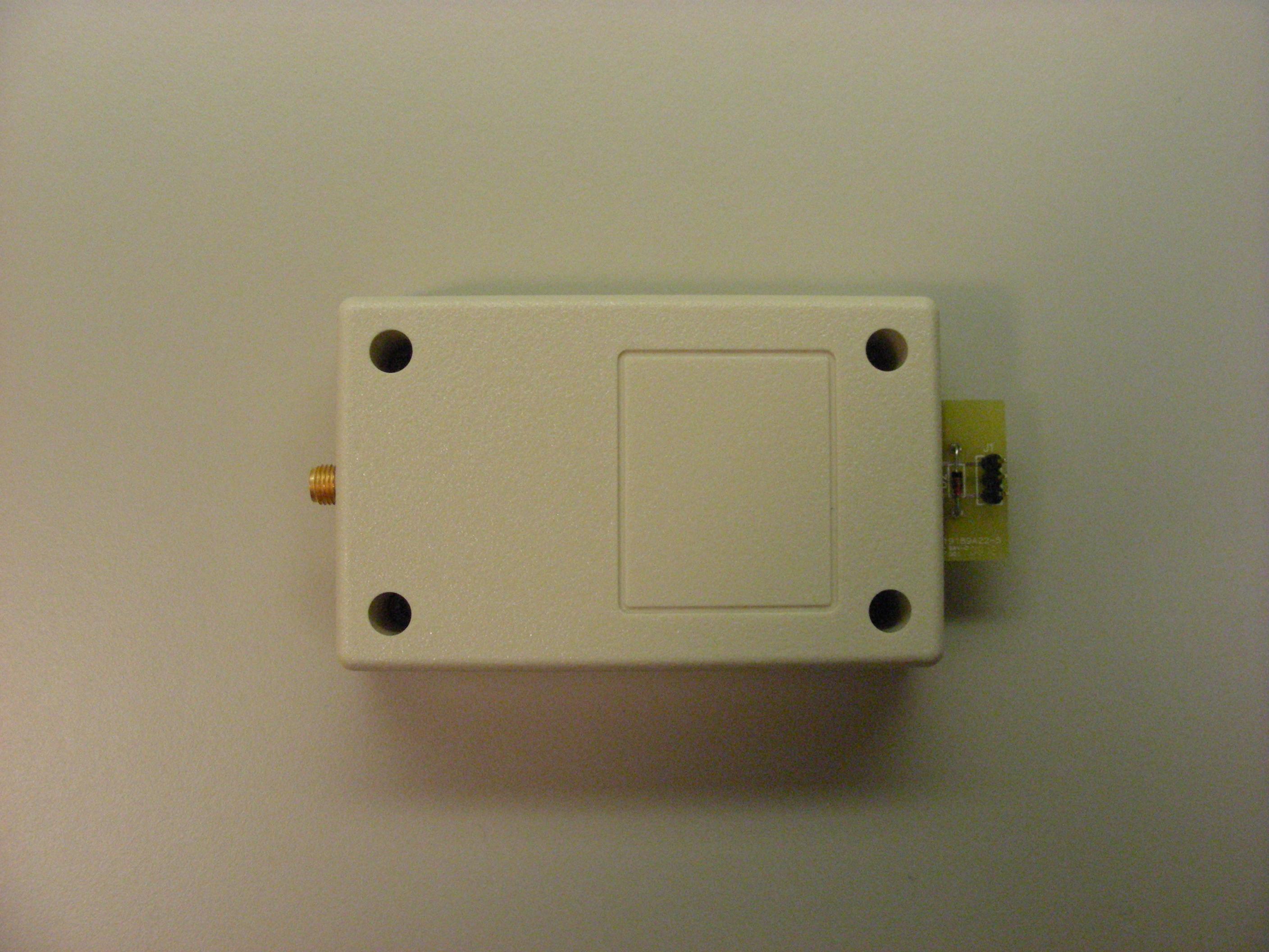
Rectifier circuit board during assembly: Diode Detail Completed rectifier board with enclosure: Completed rectifier ready for test: |
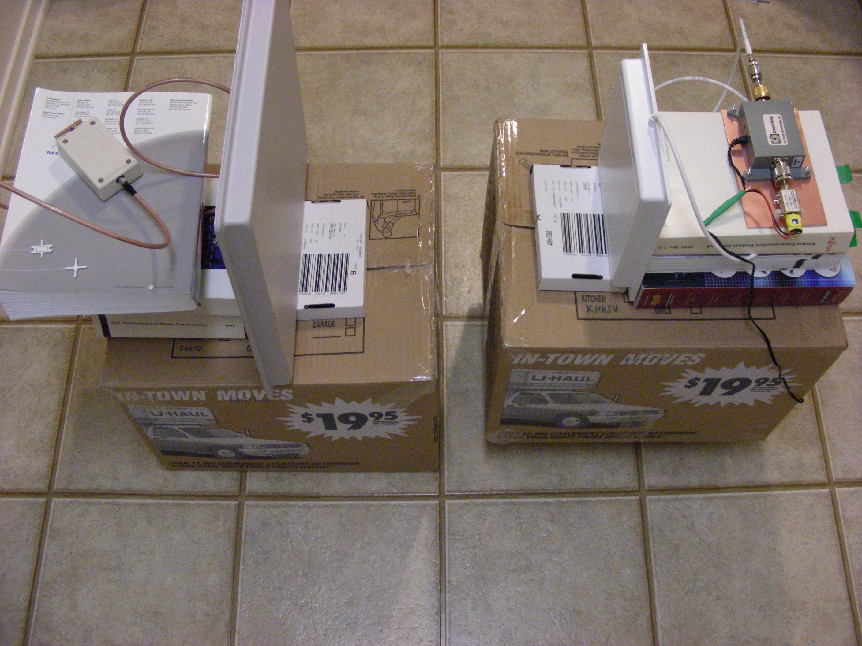
Testing of the electronics was completed on May 4, 2008.
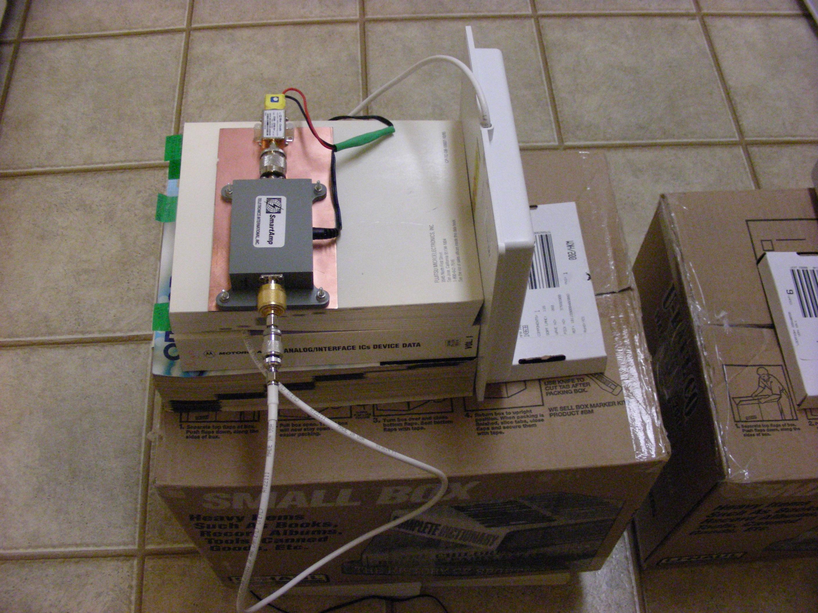
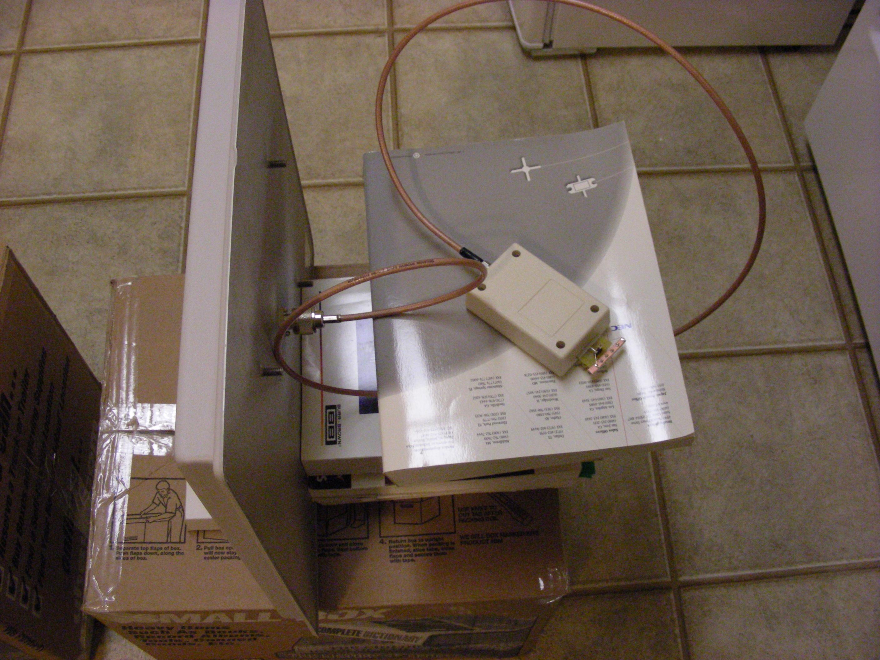
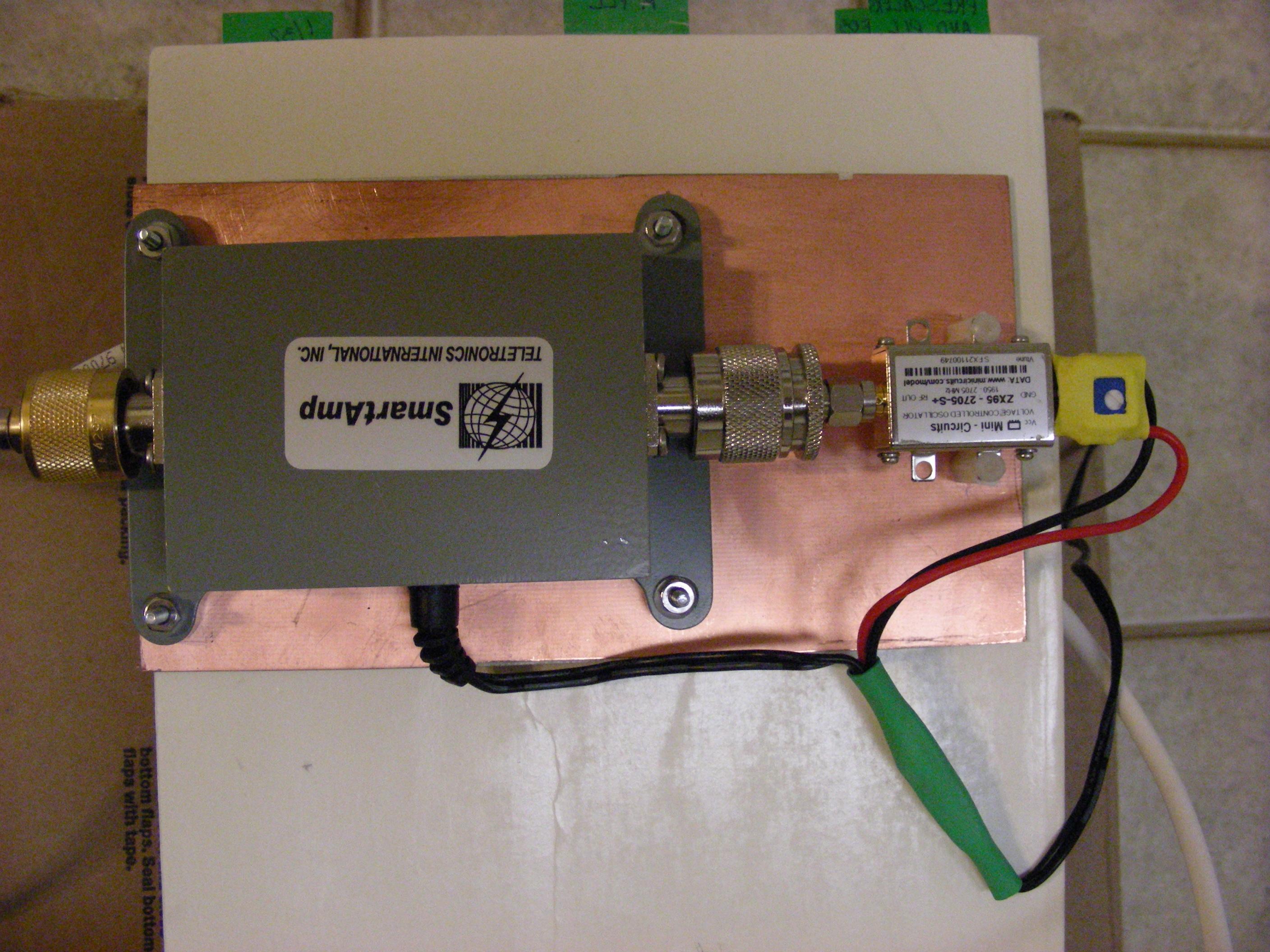
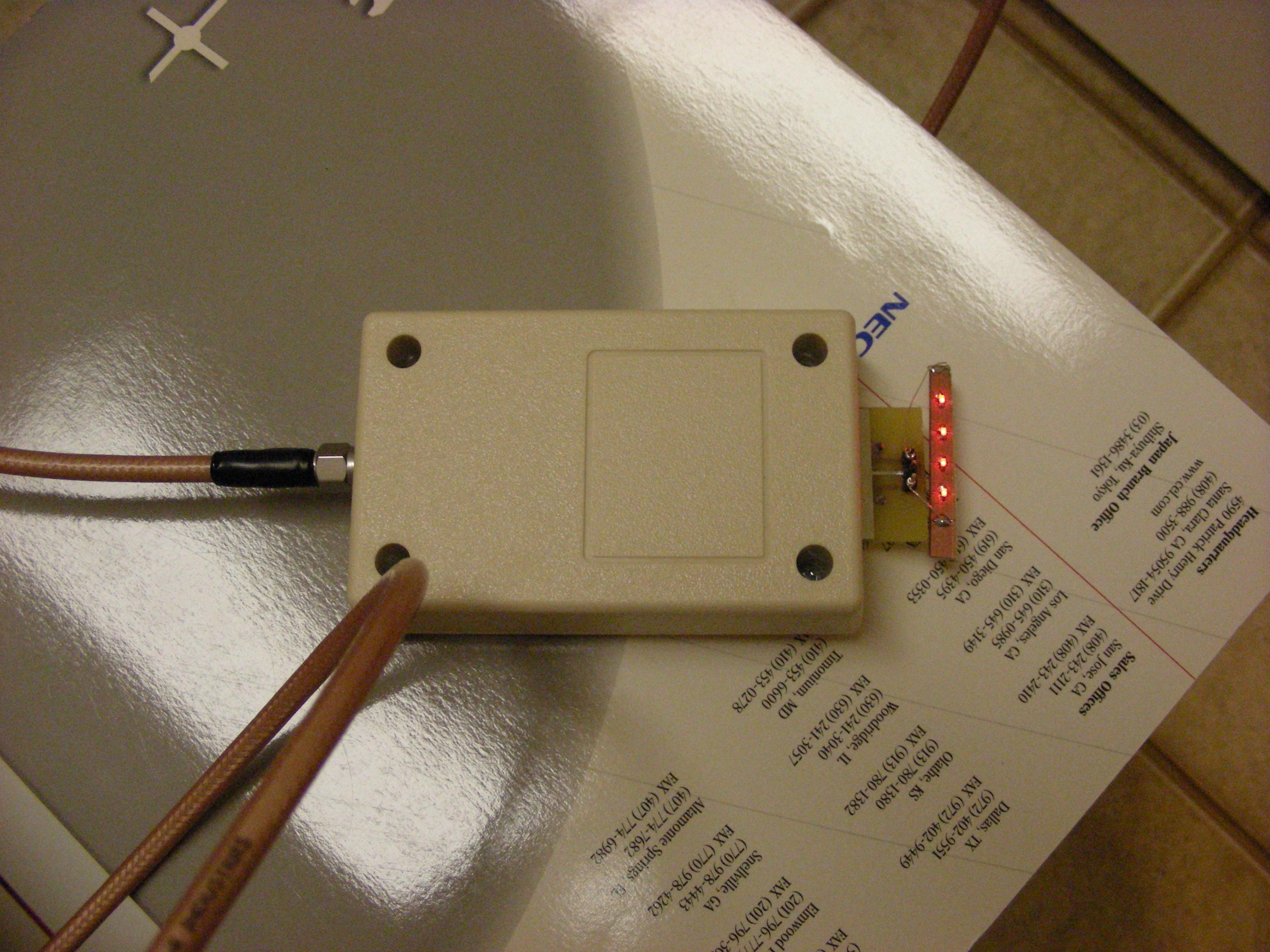
Electronics Final Test: Electronics test setup: Closeup view of the transmit half of the system. Closeup view of the receive half of the system. Closeup view of the transmitter electronics. Closeup view of the rectifier in operation driving four LED's. IT WORKS!!!!!! |

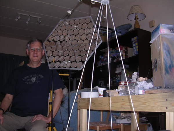
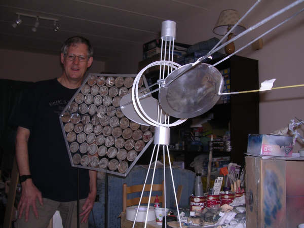
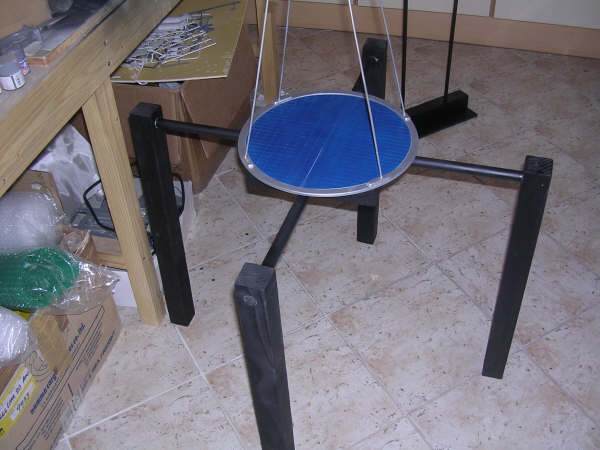
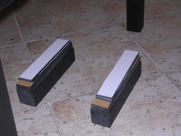
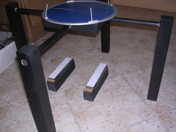
Meanwhile, Philip Mills has been hard at work constructing the stand.
Views of the stand.
The transmit antenna will be attached to the underside of the support structure under the blue disc aimed downward. The receive antanna will rest on the two rails on the floor aimed upward. The stand is about 8 feet wide, 3 feet deep and 5 feet high. |

Phase 3
Phase 3 has not been started. The number of systems to be constructed will depend on the level of funding we are able to reach and the level of interest by other organizations in obtaining a system.This is a work in progress. Check back soon for updates!
